

What changes at the edge?
Deburring removes unwanted protrusions. Edge rounding creates a curved transition. Chamfering produces an angled face. These terms describe different requirements that can occur on the same part. A process may combine them, so judge the result against the drawing and the agreed inspection method.
A deburred edge can retain a sharp corner. Rounding changes that corner into a radius, while a chamfer gives it a sloping face with a specified size and angle when required. Chamfering can also remove a burr as the material is cut away.
Incoming edge with burr
Deburred edge
Rounded edge
Chamfered edge
The sections illustrate the geometry at one edge. The dashed lines show the original nominal corner. Actual edge removal, radius or chamfer dimensions come from the part requirement and the approved process.
| Requirement | What to specify | What to inspect |
|---|---|---|
| Deburring | Edges to treat, acceptable residual burr and permitted edge change. | Residual protrusions and affected functional dimensions. |
| Edge rounding | Target radius or edge condition, tolerance and coverage. | Profile, consistency and the required inner and outer edges. |
| Chamfering | Location, size, angle, tolerance and measurement convention. | Bevel dimensions and their relationship to the mating feature. |
Surface texture is another requirement to record. A brushed face and a measured edge radius are separate inspection items. The finish on the broad face may look uniform while an internal corner still needs attention.
Choose the edge from the part's next operation
Consider a laser-cut mounting plate with an exposed outer edge, assembly holes and a larger internal opening. Mark what each edge must do before choosing the finishing process. One plate may need different treatments in different locations.
Edges handled during assembly or use
Define the intended edge condition for surfaces that people handle and for openings near cables or hoses. Specify the relevant locations and acceptance method. For moving cables, review the complete interface, including any liner, grommet or guide required by the design.
Edges that will be painted or powder coated
Rounding can improve the transition over a sharp corner and help the coating achieve suitable coverage there. Select the edge requirement with the coating process, pretreatment and service conditions in mind. A representative coated sample should show how the prepared edge performs.
Keep cleanliness and edge geometry on the same process plan. Oil, abrasive residue and laser-generated oxide may require specific preparation. Confirm that the proposed route addresses each condition, then perform the coating checks required for that part.
Hole entries and mating features
A chamfer may provide a defined lead-in for an assembly feature. Check the specified angle and size together with the remaining straight bore or contact surface. On a locating hole, sealing land or thin edge, agree how much material may be removed without losing the required fit.
On our example plate, the assembly-hole entrance and the precision locating hole have different jobs. Mark any features requiring selective treatment or protection. A general brushing pass can contact several edges, so confirm how the process will preserve the features with tighter limits.
Turn the drawing note into an inspection requirement
Review notes such as “remove burrs” or “break sharp edges” before running the order. Identify the applicable edges, the permitted material removal and how acceptance will be decided. A repeat order is easier to control when those details stay with the drawing revision.
| Drawing note | Details to agree before production |
|---|---|
| Remove burrs | Coverage, residual-burr criterion, allowed edge change and critical dimensions. |
| Break sharp edges | Permitted edge form, size range, locations and inspection method. |
| Specified radius | Radius range, continuity, applicable faces and profile measurement. |
| Specified chamfer | Angle, size reference, tolerance and which hole entry or outer edge is included. |
| Specified face finish | Visible face, texture direction, appearance or roughness requirements. |
For a chamfer, show how its size is measured. A dimension along the original face differs from the width measured across the sloping surface. Use the drawing convention consistently in the inspection report.
For edge rounding, identify the cross-sectional edge that needs a radius. A rounded corner in the flat DXF describes the part's plan-view outline. The finishing requirement concerns the transition between the plate face and its cut edge.
Keep a marked edge map with the order. It should identify the top and bottom faces, internal features, protected areas and cosmetic surfaces. Have design and quality personnel resolve conflicting requirements before the sample is approved.
How do abrasive belts and brushes work on the part?
Abrasive tools remove material where they contact the workpiece. Belt and brush configurations differ in contact shape, compliance and direction of action. Abrasive selection, pressure, feed, tool condition and the incoming edge all influence the result.
Belts can be used to remove protruding material and work the broad face. Flexible brushes or other edge-processing tools can reach the transition at accessible contours. The actual tool arrangement determines which faces and edge locations are processed.

Use the two official demonstrations to follow how the part is presented and where the tools act.
- Watch the GWEIKE deburring demonstration and observe the workpiece presentation and the visible surface and edge results.
- Watch the HRD-SR600 demonstration from 0:26. The clip shows the working head, a sample close-up around 0:42 and the brush roller around 0:59.
Use these views to ask about contact and process configuration. Establish a specified radius or chamfer with a measurement suited to the drawing tolerance. A close-up photograph can document appearance, while the dimensional record establishes the profile.
The HRD-SR600 video identifies its demonstration model. The linked equipment page presents a configuration whose model and specifications should be confirmed for the quotation. Keep the quoted machine, tool arrangement and sample result together.
Check outer edges, holes and both faces
Inspect an outer straight edge, an outside corner, a representative hole and the narrowest relevant internal feature. Tool access and the direction of contact can differ at each location. The most accessible outside edge alone gives an incomplete picture of coverage.
Record which face enters the machine first. If the drawing requires treatment on both sides, determine whether the proposed machine processes them together or requires a second pass. Include turning, repositioning and the second inspection in the production trial.
Small parts, narrow strips and parts with large openings need a suitable holding arrangement. Match that arrangement to the material as well as the shape. Confirm how non-magnetic stock will be retained when evaluating a setup that offers magnetic holding.
Check flatness and the incoming burr condition. Heavy attached residue may need a preparation step before the selected finishing tools can produce the intended edge. If incoming conditions vary considerably, review the cutting process as well. The fiber laser cutting parameter guide helps frame that upstream check.
Compare samples with the same starting condition
Choose blanks from the same material and cutting condition. Record the grade, thickness, drawing revision and burr-bearing face. Include features that represent both the normal work and the difficult areas on the job.
Photograph the same locations before and after processing, using consistent orientation and magnification. Keep an untreated reference and identify each trial sample so results remain traceable to the setup.
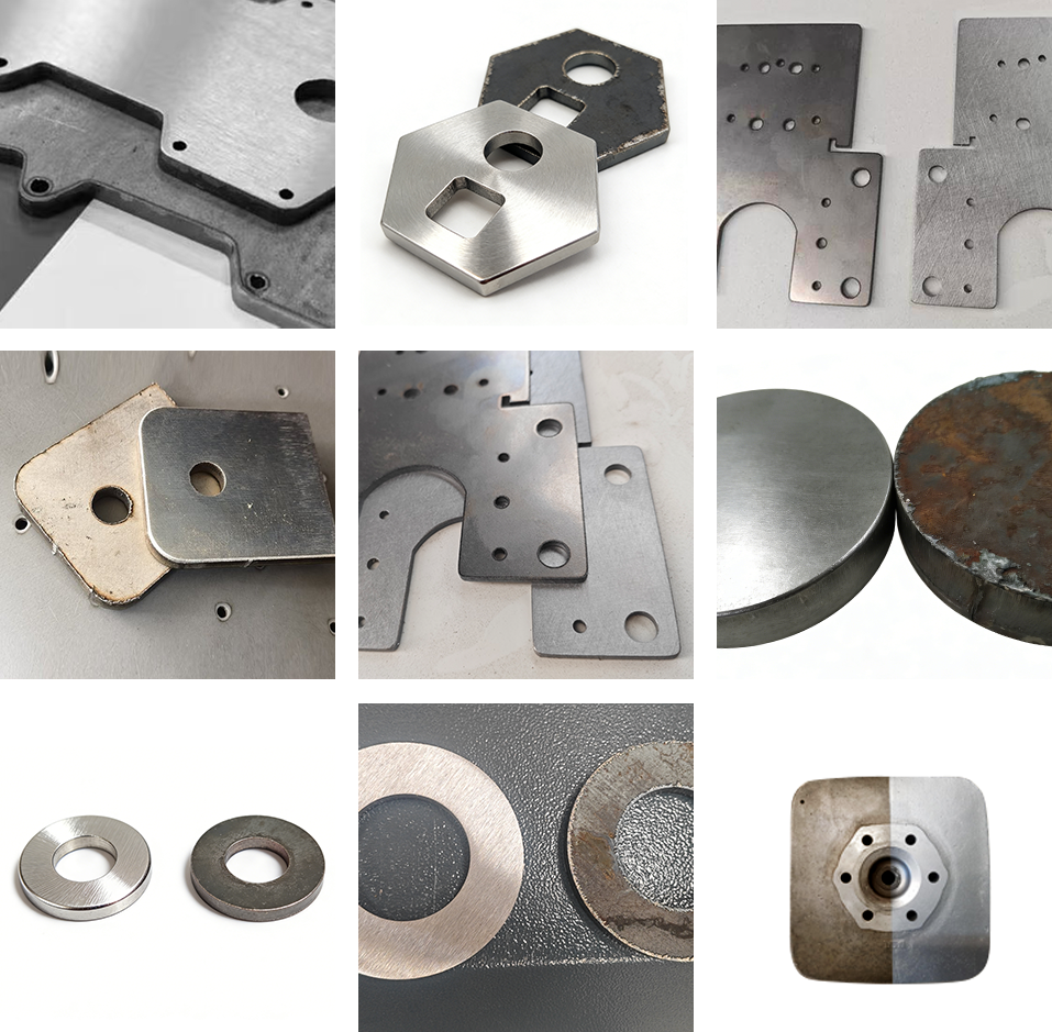
Agree on the inspection method before the trial. Depending on the required size and tolerance, this may involve magnified examination, an appropriate gauge or optical profile measurement. Use dimensional checks for specified geometry and a representative assembly or coating test where function depends on the next operation.
| Trial record | What to retain |
|---|---|
| Incoming condition | Material, thickness, cutting condition and photographs of the selected edges. |
| Burr removal | Residual-burr findings at the agreed inspection locations. |
| Radius or chamfer | Measured profile, size and angle where specified. |
| Coverage | Results for outer edges, holes, slots and each required face. |
| Protected dimensions | Hole, contact-area, thickness or flatness checks affected by processing. |
| Downstream result | Relevant assembly, forming, appearance or coating acceptance. |
| Production setup | Machine configuration, tools, settings, passes, handling and elapsed time. |
Inspect representative parts at agreed intervals during a batch to see whether the result changes with tool condition. Keep any settings adjustment in the record. This helps turn an approved sample into a repeatable process.
Compare output as accepted parts delivered to the agreed next operation. Include loading, turning, additional passes and inspection in the elapsed period. A repeat pass that is required to finish the inner contours belongs in the production calculation.
Match the machine to the required finish
Build the equipment review around the edge map and the approved sample. Confirm processing range, minimum stable workpiece size, holding method, tool access and the ability to preserve the functional features on your drawing.
Check the proposed configuration against your material mix and normal batch sizes. Record how tools, settings and handling change between jobs. For short batches, those changes may account for a substantial part of the available production time.
If the drawing requires a tightly controlled chamfer size and angle, ask the supplier to demonstrate that feature using the proposed tooling and inspection method. Establish whether the quoted route includes any separate operation needed to meet it. Apply the same review to a specified edge radius.
Use the quotation to identify the exact machine and included process stages. Attach the sample report and agreed acceptance conditions so later equipment discussions refer to the same result.
Send your part and edge requirements
Share the drawing, material and thickness, photographs of the incoming edges and your usual batch size. Mark which edges need deburring, rounding or a specified chamfer, and identify the dimensions and surfaces that must be preserved.
Ask GWEIKE to propose a configuration and sample trial covering the required faces, difficult features, inspection method and production time. Include the next operation so the finished edge can be evaluated in its intended use.