

Which speed and which accuracy does the specification describe?
Rapid traverse describes machine motion. Cutting feed describes progress along a cut. Positioning specifications describe measured axis behavior under stated conditions. A purchasing comparison needs those definitions alongside the cycle time and measured quality of your parts.
Start by keeping the original label beside every number. Ask whether a speed or acceleration is specified for one axis or simultaneous motion, under what conditions it applies, and which configuration was tested. Confirm the measurement method and travel range behind an accuracy figure.
| Term | What it describes | What to check |
|---|---|---|
| Maximum rapid traverse | Fast positioning, typically between cutting operations. | Axis or simultaneous rating, move length and actual travel time. |
| Cutting feed | Programmed or actual travel along the cutting contour. | Material, thickness, gas, geometry and acceptable edge quality. |
| Acceleration | How quickly velocity changes. | Applicable motion settings and performance on short moves and direction changes. |
| Positioning accuracy | How closely achieved positions match commanded positions under a defined test. | Test method, measured range, conditions and report. |
| Positioning repeatability | How consistently the axis returns to a position under defined conditions. | Repeat-test conditions and the reported variation. |
| Finished-part conformity | Whether the manufactured part meets its drawing and quality requirements. | Dimensions, feature locations, contours and cut-edge condition. |
For an accuracy claim, ask whether the value applies over the full specified travel or a stated test length. Check whether repeatability was evaluated from one approach direction or both, and whether compensation was active. Keep the supplier’s reporting convention and test conditions with the value rather than reducing the report to a single number.
Acceleration expressed in G uses gravitational acceleration as a reference: 1G is approximately 9.81 m/s². A higher maximum acceleration can help relevant moves, but its ratio to another machine's rating is not a production-output multiplier.
Also distinguish commanded feed from achieved feed. A controller can reduce speed for motion or process reasons. The actual program includes piercing, travel, height checks and other actions in addition to contour cutting.
Long straight edges and short contours ask different things of the machine
A long uninterrupted edge gives the head more distance to build speed and, where the process allows, maintain a steady cutting feed. The usable feed still depends on the material, thickness, laser process and required edge quality.
Short slots, small arcs and frequent changes of direction place different demands on the motion system. Acceleration, deceleration and path planning can occupy a larger share of the movement. A short move may finish before the selected speed is reached.
A · Long straight sections
Room to sustain a feed where the process allows.
B · Short slots and small arcs
Frequent changes in direction and short feature paths.
These two shapes illustrate different motion demands. They are not equal-length test parts or a measured comparison. Use features from your own production drawings when deciding which behavior matters.
Illustrative moves starting and ending at rest, with no numerical scale. Continuous contours can carry speed through transitions; actual motion profiles depend on the controller, geometry and permitted deviation.
The head does not have to stop at every corner. Look-ahead and contour-control strategies determine how neighboring moves are joined. Even at a steady speed around a circular path, the direction of motion changes, so the axes continue to accelerate.
Consider the process limit as well. When material and edge requirements call for a relatively low cutting feed, additional rapid-traverse capability may mainly affect movement between contours. Where the process permits a higher feed but the geometry repeatedly demands speed changes, dynamic performance becomes a more relevant question. The representative drawing determines which limitation to investigate.
Include a representative long edge and a group of short features in the trial. Check the resulting corners and holes as well as the clock. The GWEIKE speed demonstration offers a useful starting point for observing complete programmed runs.
Why the bed, beam and control settings belong in the discussion
The motion system must move the cutting head while controlling its path. Structural stiffness, moving mass, drive response and vibration behavior all contribute. A large acceleration figure alone does not describe that complete system.
Jerk describes how quickly acceleration changes. Controlled acceleration ramps help manage the excitation of vibration, while the chosen profile also affects move time. Ask how the proposed settings preserve the contours and edge condition required by your drawing.
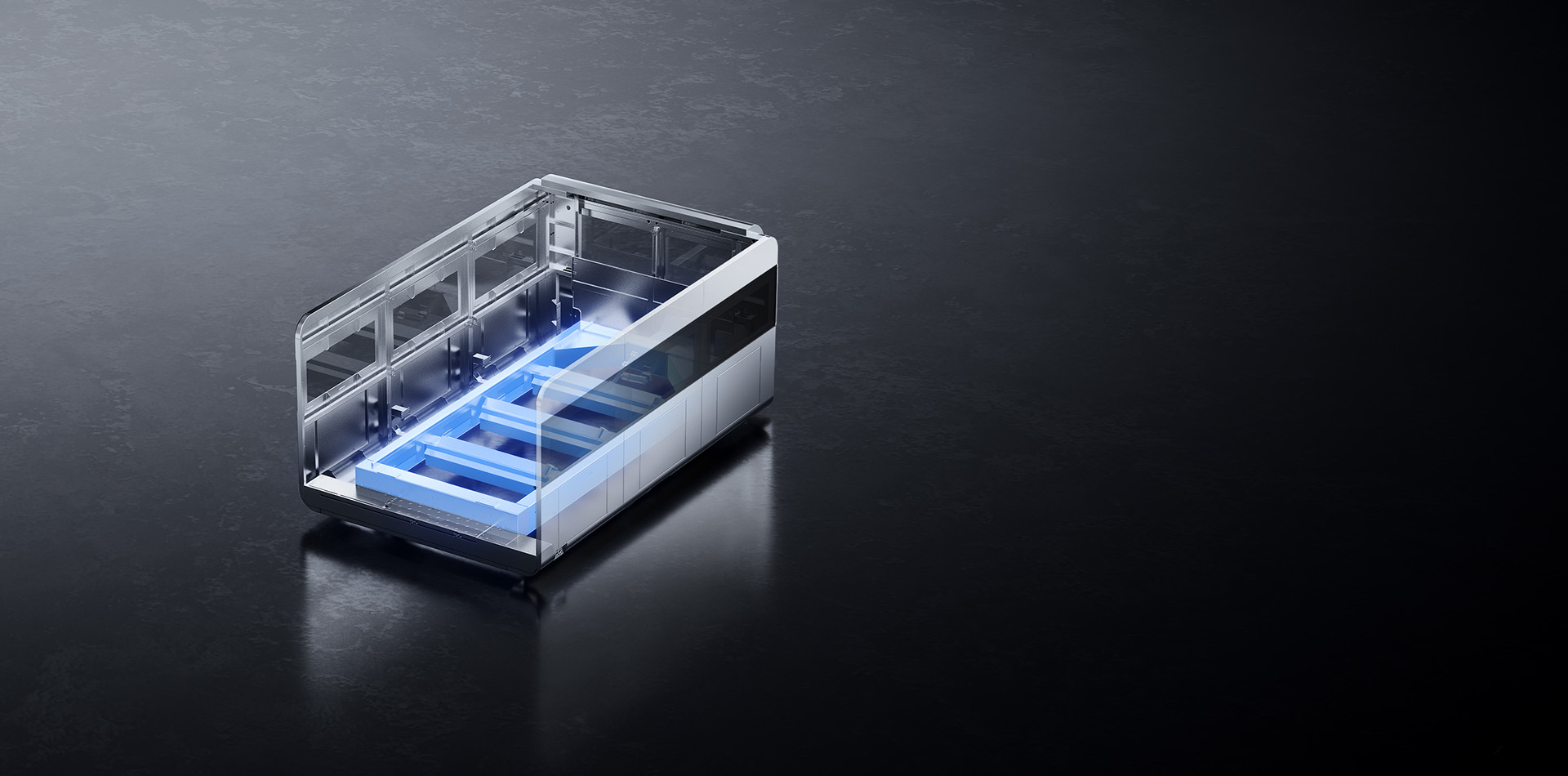
The GV bed and structure video introduces the physical design behind the machine. Use the structural explanation to frame questions about dynamic performance, then check the result on a timed and measured sample.
A filter setting expressed in Hz describes a control parameter. It is not the number of cutting movements per second or a direct measure of part accuracy. Keep it attached to the relevant controller and configuration; comparing isolated frequency values gives an incomplete picture.
Separate axis specifications from the dimensions on your drawing
Positioning accuracy and repeatability answer different questions. An axis can return consistently to a location that remains offset from the commanded position. Repeatability describes the consistency of those returns; accuracy concerns their relationship to the intended positions.
The finished part adds further influences, including kerf compensation, thermal effects, material condition, support and cutting parameters. A published positioning tolerance therefore does not establish the same tolerance for every cut feature.
Choose a representative mounting plate and mark the features that matter to assembly. Identify the drawing references used to locate them, the required tolerances and the measurement method before cutting.
| Feature | Inspection focus |
|---|---|
| 1 · Outer profile | Overall dimensions, specified straightness or profile requirements, and edge condition. |
| 2 · Holes | Diameter, specified roundness and feature locations relative to the drawing references. |
| 3 · Slot and end radii | Width, length, end shape and the fit required by the mating part. |
| Across the work area | Representative features at agreed sheet positions and production stages. |
For example, a mounting plate can have two holes with acceptable diameters yet fail assembly because their locations are wrong. A slot may have the correct width through its middle while an end contour misses the specified profile. Inspect the features against their drawing references and functional requirements, rather than choosing only the easiest dimensions to measure.
Use instruments and procedures suited to the tolerance and feature. Appearance in a close-up video cannot establish a small dimensional deviation. For demanding profiles or hole locations, agree on appropriate optical or coordinate measurement, including measurement uncertainty where relevant.
Record machine warm-up, the production stage and the part condition during measurement. Compare repeat samples at agreed locations, with consistent support and temperature conditions. Report the full results, including variation and any rejected features.
Repeated part measurements assess process consistency. They do not replace a formal axis positioning or repeatability test. Ask for the machine test report and the part inspection report as separate evidence.
Read the conditions behind a timed demonstration
Before comparing stopwatches, identify the material, thickness, laser power, gas, geometry and timing boundaries. Record which motion and process settings differ. Confirm whether the displayed time covers the complete program or only a selected cutting sequence.
In the GV split-screen demonstration, the runs are labelled 6 kW, 1 mm stainless steel and nitrogen. The displayed motion settings are 3.0G / 10 Hz and 0.6G / 6 Hz. Both acceleration and filtering differ, so the observed result belongs to those configurations and conditions.
The clip provides a reason to test similar geometry on a shortlisted machine. It does not isolate the effect of acceleration alone or establish every dimension on the finished sample. Link each timed result to its measured part and saved program settings.
For a production comparison, retain rejected parts, repeat runs and interruptions in the record. Define how they are counted before testing so a fast selected sequence does not obscure the result of the agreed job.
Use the same task and acceptance criteria for each test cut
Give each supplier the same drawing revision, material requirements and part-quality target. Include a long contour, short features and critical dimensions that represent your normal work. A production drawing provides stronger purchasing evidence than a pattern chosen only to look fast.
Allow each machine to use an appropriate qualified program and process, while documenting the differences. Different controls may require different postprocessors and motion settings. Forcing identical acceleration settings can conceal the capability you are trying to evaluate.
| Agree before cutting | Record with the result |
|---|---|
| Drawing and quantity | DXF revision, nest, quantity, critical dimensions and acceptance limits. |
| Stock | Material grade, thickness, sheet format and surface condition; matched batch where practical. |
| Machine configuration | Model, laser power, cutting head, control and relevant software versions. |
| Gas and process | Gas type, supply conditions and the selected cutting process. |
| Program strategy | Piercing, lead-ins, common-line cutting, microjoints, fly cutting and relevant compensation. |
| Timing boundaries | Program start and finish; loading, unloading and sorting recorded separately. |
| Inspection | Features, locations, instruments, method and part measurement conditions. |
| Repeat runs | All agreed runs, interruptions, rejected features and any rework. |
| Traceable evidence | Sample IDs, original time records, measurements and saved settings. |
Keep the permitted contour deviation fixed. If one program blends a corner or changes a small feature, confirm that the result remains within the drawing requirement. Preserve the intended part geometry and feature count. Record programming changes such as common-line cutting so their contribution stays visible in the comparison.
Decide whether the purpose is to compare complete purchase configurations or investigate a particular factor. A motion-focused experiment should hold other relevant variables as consistent as practical. A whole-machine comparison can include different power levels, but the outcome then reflects the complete configurations.
Review cut-edge condition alongside dimensions: burrs, dross, local overheating and other drawing-specific requirements can affect acceptance and downstream work. A part that needs an extra finishing step changes the production comparison.
Keep the program-time result separate from the complete job cycle. Note how each platform is loaded and cleared, then include those tasks when evaluating shift output. Save the accepted samples and reports with the proposed configuration.
Use the GV and CV specifications to build a shortlist
GWEIKE's published pages provide the following motion references. Confirm the current model-specific technical agreement, rating basis and test conditions before comparing quotations.
| Published item | GV reference | CV reference |
|---|---|---|
| Maximum speed field | 200 m/min; page identifies maximum rapid speed. | 175 m/min; table labels maximum X/Y axis speed. |
| Maximum acceleration | 3G | 2G |
| X/Y positioning accuracy | ±0.03 mm | ±0.03 mm |
| X/Y repeat positioning accuracy | ±0.02 mm | ±0.02 mm |
These are the published fields on the GV product page and CV single-platform laser cutter page. Verify single-axis versus simultaneous ratings where relevant. Matching positioning figures do not establish identical outcomes on every part.

The CV cutting demonstration shows the machine working through contours and holes. Apply the same timing and inspection plan when evaluating a CV configuration for your drawings.
Choose the trial mix from the orders you expect to run. A thin plate with many holes can reveal dynamic behavior, while another material or geometry may be limited mainly by the cutting process. Include both when both matter commercially. Review the results against your expected order mix before using one demonstration to justify the purchase.
Shortlist by processing range, part requirements, handling arrangements, expected job mix and investment scope. Then use the measured trial to determine whether the proposed motion performance produces a useful benefit on that work.
Bring your drawing to the machine comparison
Send GWEIKE your DXF, material and thickness, critical tolerances and normal batch quantity. Mark the long contours, short features and assembly dimensions that drive the decision.
Request a proposed GV or CV configuration with an agreed trial program, timing boundaries and dimensional inspection record. Keep the measured sample and time result together.