Table of Contents
- Use This Guide with GWEIKE M-Series
- What Makes Laser Welding Fail?
- Surface Defects
- Internal Defects
- Geometry Defects
- Material-Specific Problems
- How Parameters Affect the Weld Pool
- Quick Troubleshooting Checklist
- Adjust Parameters vs. Change the Process
- Related Articles
- FAQ
- Plan a Laser Welding Trial with GWEIKE
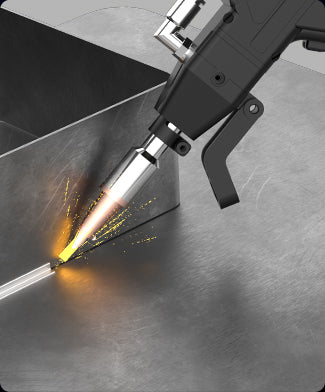
Use This Guide with GWEIKE M-Series 6-in-1 Welders
Stainless, carbon steel and aluminum settings are validated on GWEIKE M-Series fiber welding systems.
What Makes Laser Welding Fail?
Most laser weld issues fall into four groups:
- Surface defects – burn marks, heavy discoloration, spatter.
- Internal defects – porosity, lack of fusion, cracks.
- Geometry defects – undercut, undersized welds, excessive reinforcement.
- Distortion and fit-up problems – parts pulled out of tolerance, open gaps.
The root causes usually sit in the same limited toolbox: power, speed, beam oscillation pattern, shielding gas and joint preparation. The art is knowing which knob to turn first.
Need the full context (materials, joint types, parameter logic, defect map)? Start with our Laser Welding Complete Guide (2026), then come back here for symptom-based troubleshooting.
Key Idea – Change One Thing at a Time
When troubleshooting laser welding, change one parameter at a time and check the result on cut sections or bend tests. Random, multi-parameter changes eat time and hide the real cause.
Surface Defects – Burn Marks, Discoloration and Spatter
Symptom
Weld bead and heat affected zone (HAZ) show dark blue or black colors. Cosmetic parts require heavy grinding or polishing to meet finish requirements.
Likely Causes
- Shielding gas flow too low or nozzle too far from the weld.
- Excessive heat input: peak power too high, travel speed too slow, or oscillation frequency too low.
- Gas type not optimized (e.g. oxygen on stainless when appearance matters).
Practical Corrections
- Increase nitrogen flow (aim for a stable range such as ≥ 20 L/min at the nozzle).
- Reduce peak power in small steps and/or slightly increase travel speed.
- On thin stainless (0.5–1.5 mm), increase oscillation frequency and avoid very slow, high-heat passes.
- Use a suitable gas for stainless when color and corrosion resistance are critical.
Symptom
Holes, edge collapse or severe undercut on thin sheet, especially on 0.5–1.0 mm stainless or aluminum.
Likely Causes
- Energy density too high: peak power or duty cycle set too high for the thickness.
- Travel speed too low, especially at corners and part edges.
- Oscillation scan width too narrow, concentrating heat at a single line.
- Large gaps between parts, so molten metal drops out of the joint.
Practical Corrections
- Increase oscillation frequency and widen the scan by 0.3–0.5 mm to spread heat.
- Reduce peak power in 2–3 % steps until burn-through stops but root fusion remains.
- Increase travel speed slightly when entering thin, unsupported edges or small tabs.
- Improve fixturing and fit-up; close large gaps that the weld cannot bridge.
Symptom
Small metal droplets around the weld, sticking to the surface and coating optics or fixtures.
Likely Causes
- Too much keyhole instability due to very high power and low travel speed.
- Gas jet misaligned, pushing the molten pool rather than shielding it.
- Contaminated surfaces (scale, heavy rust, oil) creating explosions in the melt pool.
Practical Corrections
- Reduce peak power slightly or increase speed to bring the process out of an unstable regime.
- Verify gas nozzle alignment and distance; adjust to blow along the joint, not directly into the pool.
- Improve cleaning: remove scale, rust and oil before welding.
Internal Defects – Porosity and Lack of Fusion
Symptom
Gas pores visible in macro-etches or X-ray inspection. Porosity may appear clustered or along the entire weld length.
Likely Causes
- Contamination: oil, paint, moisture or oxide layers in the joint.
- Weak or unstable shielding gas flow, allowing air to enter the weld pool.
- Unstable wire feed (for wire-fed laser welding), causing turbulence in the melt pool.
- For aluminum: oxide layer not removed, releasing gas during melting.
Practical Corrections
- Introduce a consistent cleaning process: mechanical (brushing, grinding) plus solvent, especially on aluminum and stainless.
- Increase gas flow moderately and reduce nozzle stand-off to improve shielding.
- Check wire feed system for slipping, kinks or worn liners; stabilize feed speed.
- On aluminum, remove oxide shortly before welding and avoid long delays between cleaning and welding.
Symptom
Welds pass visual inspection but fail bend tests or destructive pull tests. Cross-sections show incomplete penetration or lack of fusion at the root or side walls.
Likely Causes
- Insufficient energy input: power too low or travel speed too high.
- Oscillation scan width too wide, spreading energy without enough depth.
- Focus position too high above the surface, reducing penetration.
- Poor joint fit-up, especially on fillets and gaps at the root.
Practical Corrections
- Increase peak power in small steps and/or reduce travel speed until cross-sections show full fusion.
- Reduce scan width slightly to concentrate energy in the joint.
- Adjust focus closer to the material surface or slightly into the joint for thicker sections.
- Improve joint preparation and clamping to remove excessive gaps.
Geometry Defects – Undercut, Undersized Welds and Distortion
Symptom
A groove forms along one or both sides of the weld bead, reducing effective throat thickness.
Likely Causes
- Heat concentrated at the surface: high power with narrow scan width.
- Travel speed too high, not allowing enough filler to build up the edges.
- Joint geometry or torch angle pulling the molten metal away from the toes.
Practical Corrections
- Widen scan width slightly and reduce power or speed to let molten metal wet the toes.
- For wire-fed welding, increase wire feed to fill the joint edges.
- Optimize torch angle or beam path to keep the oscillation centered in the joint.
Symptom
Parts warp or pull out of tolerance after welding. Thin panels show visible bowing or twisting, even with laser’s lower heat input.
Likely Causes
- Excessive overall heat input due to long continuous welds on thin sheet.
- Unbalanced welds: heat applied on one side only with no counter-welds or fixtures.
- Clamping insufficient to hold the part in position during cooling.
Practical Corrections
- Break very long welds into intermittent welds or staggered runs where design allows.
- Reduce power and increase speed where full penetration is not structurally required.
- Add fixtures or backing bars to stabilize thin panels during welding and cooling.
Material-Specific Problems
Stainless Steel – Burn-Through and Discoloration
On 0.5–4 mm stainless sheet, the most frequent complaints are weld burning on thin panels and heavy blue/black discoloration on visible parts.
- Use a stable parameter window tailored to thickness, rather than guessing settings.
- On thin sheet, prioritize higher oscillation frequency and careful control of peak power.
- Keep nitrogen shielding gas flow in a proven range and maintain correct nozzle stand-off.
For detailed stainless settings and cross-section examples, see:
Stainless Steel Laser Welding Guide
Carbon Steel – Black Welds and Spatter
Carbon steel welds often suffer from black, oxidized surfaces and spatter if gas type and parameters are not matched to the application.
- Choose the right shielding gas: pure oxygen for cutting speed, but inert or mixed gases when weld quality matters.
- Limit heat input by optimizing power, speed and spot/oscillation size.
- Remove heavy rust and mill scale before welding to reduce spatter and improve wetting.
Aluminum – White Smoke, Porosity and Incomplete Fusion
Aluminum is more sensitive to preparation and shielding than steel. Common issues include white smoke, surface soot, porosity and lack of fusion.
- Always remove oxide layers and contaminants shortly before welding.
- Use appropriate gas (usually argon or argon mixes) and maintain stable flow.
- Target higher travel speeds combined with sufficient power to avoid excessive heat build-up.
A dedicated aluminum welding guide can provide starting parameters for the 1–3 mm range and recommended cleaning workflows.
For detailed Aluminum examples, see:
Industrial Aluminum Laser Welding Guide
How Parameters Affect the Weld Pool
Every correction in the previous sections boils down to a few core parameters. Understanding how they change the weld pool makes troubleshooting faster and more repeatable.
Power and Duty Cycle
Power and duty cycle directly control the heat delivered to the material. Higher values increase penetration but also the risk of burn-through, distortion and wide HAZ.
Travel Speed and Wire Feed
Travel speed sets line energy (J/mm). Too fast, and the weld becomes weak; too slow, and defects like burn-through and excessive reinforcement appear. With wire feed, speed must be balanced against deposition rate to avoid undercut or excessive buildup.
Oscillation Frequency and Scan Width
Oscillation frequency shapes how “smoothly” energy is spread in the pool. Higher frequency generally stabilizes the pool and refines the bead, while lower frequency allows deeper penetration but can increase instability. The scan width controls bead width and heat distribution at the toes of the weld.
Gas Type and Flow
Shielding gas is not just a corrosion or color issue. Poor shielding promotes porosity, surface oxides and unstable keyholes. Gas choice (nitrogen, argon, oxygen or mixes) and flow must match both material and process.
Use Parameters as a Window, Not a Single Point
For each material and thickness, work with a parameter window, not one “magic” setting. For example, stainless 2.0 mm may weld reliably in a range of peak powers and frequencies – staying inside that window is more important than hitting a single number.
Quick Troubleshooting Checklist (Shop-Floor View)
Match what you see on the part to the row below, then adjust one parameter at a time.
| Symptom | Most Probable Causes | First Adjustments to Try |
|---|---|---|
| Burn-through / edge collapse |
|
|
| Dark or black weld on stainless |
|
|
| Porosity |
|
|
| Weak weld / lack of fusion |
|
|
| Undercut |
|
|
| Distortion / panel warp |
|
|
When to Adjust Parameters vs. Change the Process
Not every defect is solved by turning knobs on the laser. In many cases the process itself needs to change: joint design, fixture concept, or even switching from autogenous welding to wire-fed welding.
- Use parameter changes when defects are moderate and consistently related to heat input or gas.
- Review joint design when gaps, access or geometry make the weld inherently unstable.
- Add filler wire when underfill, undercut or fit-up issues cannot be solved with autogenous welding alone.
- Improve fixturing when distortion or alignment issues dominate quality problems.
Use this map to move from symptoms → parameters → process selection.
FAQ
These are the most common questions operators ask when a weld looks “almost right” but still fails in production.
Why does stainless steel turn blue/black after laser welding?
How do I prevent burn-through on 0.5–1.0 mm sheet?
My weld looks fine visually, but fails a bend test—why?
What are the main causes of porosity in laser welding?
Which shielding gas should I use for stainless, carbon steel, and aluminum?
How do oscillation frequency and scan width affect weld quality?
What should I fix first: parameters or joint fit-up?
How can I reduce spatter and protect optics/fixtures?
Plan a Laser Welding Trial with GWEIKE
Share your material, thickness range and typical defects – our team can validate process windows on an M-Series system.