Users searching for laser cleaning parameters often expect a table of exact settings — specific power levels, speeds and frequencies for each material. In practice, handheld laser cleaning does not work that way. Settings that clean stainless steel weld oxide effectively may be insufficient or excessive for the same job on a different surface condition, contamination thickness, or operator travel speed.
This guide explains how parameters work for handheld CW (continuous wave) fiber laser cleaning systems — such as the GWEIKE LCW series — and how to find working settings safely through structured test-piece validation. For background on how laser cleaning works, see the laser cleaning guide.
Why Laser Cleaning Parameters Are Not Universal
Several variables affect what settings will work for a given job, and most of them change from one situation to the next:
- Material type — stainless steel, carbon steel, aluminum and copper absorb laser energy differently.
- Surface condition — polished, brushed, oxidized or coated surfaces respond differently even on the same base material.
- Contamination type and thickness — light HAZ oxide, heavy rust, thin paint and thick epoxy each require different energy delivery.
- Machine power level — a 1500W system and a 3000W system delivering "50% power" are delivering very different energy levels.
- Operator travel speed — in handheld operation, the speed at which the operator moves the gun directly affects how much energy reaches each area. This variable is absent in automated systems.
This is why parameters from online tables, competitor guides or automated system manuals should not be applied directly to a handheld system without testing. Always validate on a scrap piece or non-critical test area first.
CW vs Pulsed Laser Cleaning: Different Parameters
Many laser cleaning parameter guides you find online are written for pulsed laser cleaning systems — machines that deliver energy in short bursts with controllable pulse frequency, pulse duration and peak power. The GWEIKE LCW series uses a continuous wave (CW) fiber laser operating in continuous or modulated mode. The controllable parameters are different.
| Parameter type | Handheld CW fiber laser cleaning (LCW series) | Pulsed laser cleaning system |
|---|---|---|
| Power setting | Power % of rated output (e.g. 10–100% of 1500W) | Pulse energy (mJ) or average power (W) |
| Beam delivery | Continuous or modulated | Pulsed — nanosecond to microsecond bursts |
| Frequency control | Not applicable in the laser pulse sense. Some systems include scan head wobble frequency (cleaning head oscillation speed) — this is not laser pulse frequency. | Pulse repetition frequency (kHz) |
| Pulse duration | Not a user-set parameter | Pulse width (ns, μs) |
| Scan coverage | Cleaning width / scan width (0–80 mm on LCW1500A) | Scan speed and spot overlap |
| Energy per area | Controlled by power %, scan width, travel speed, number of passes | Controlled by pulse energy, frequency, scan speed, spot overlap |
Important: If you find a laser cleaning parameter table specifying "frequency 50 kHz" or "pulse duration 100 ns," those settings are for a pulsed laser cleaning system, not a CW fiber laser handheld system. Do not attempt to apply them directly to an LCW-series machine. Consult the machine manual or GWEIKE application support for guidance specific to your system.
Key Parameters for Handheld CW Fiber Laser Cleaning
For handheld CW fiber laser cleaning, five parameters control the energy delivered to the surface. They are interconnected — adjusting one typically requires reassessing the others.
Core principle: Higher power, narrower scan width, slower travel speed and more passes all increase energy delivered to the surface. Lower power, wider scan width, faster travel speed and fewer passes reduce it. Use this relationship to navigate parameter adjustments safely.
Power (%)
What it controls: The proportion of rated laser output delivered to the surface. On a 1500W system, 40% power delivers approximately 600W; on a 3000W system, 40% delivers approximately 1200W. Power setting alone does not define energy per area — it works together with scan width and travel speed.
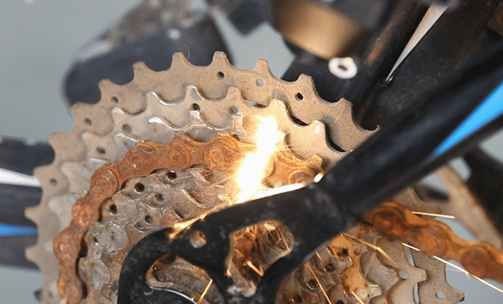
Too high: Heat marks, discoloration beyond the cleaning zone, surface roughness changes, possible warping on thin parts, sparking.
Too low: Contamination not fully removed; multiple passes required without progress.
How to adjust: Start low and increase in increments. For most applications, begin between 20–40% of rated output on a test piece and increase only if lower settings leave contamination after several passes.
Scan Width / Cleaning Width
What it controls: The width of the oscillating beam pattern at the surface. On the LCW1500A, cleaning width is adjustable from 0 to 80 mm. A wider scan distributes the same power over a larger area, reducing energy density. A narrower scan concentrates energy into a smaller area.
Too wide: Energy density may be insufficient to remove stubborn contamination; multiple passes needed.
Too narrow: Risk of localized overheating and streak marks from uneven energy distribution; slow area coverage.
How to adjust: Start wide (50–80 mm) for light contamination on flat surfaces. Reduce scan width when contamination is thick or resistant, always in combination with power and speed adjustments.
Travel Speed
What it controls: How fast the operator moves the cleaning gun across the surface. This is the most variable parameter in handheld operation because it depends on operator technique, not a machine setting. Slower travel allows more energy per unit area; faster travel reduces it.
Too slow: Excessive heat input per area — heat marks, discoloration, possible surface damage on sensitive materials.
Too fast: Insufficient energy to remove contamination; streaks or unclean areas.
How to adjust: Aim for a controlled, steady pace — neither rushed nor slow. Inconsistent speed is the main cause of uneven results in handheld cleaning. Practice on scrap material to develop a consistent movement before cleaning production parts.
Number of Passes
What it controls: How many times the beam crosses the same area. Multiple passes at lower power are generally safer than a single high-power pass, particularly on sensitive surfaces or thin material.
Too few: Contamination may not be fully removed, especially for thick rust or heavy coatings.
Too many at high power: Cumulative heat input can cause substrate effects even if individual passes seem acceptable.
How to adjust: Increase passes before increasing power. Allow the surface to cool briefly between passes on heat-sensitive materials. Record the number of passes that achieves the required result consistently.
Working Distance and Gun Angle
What it controls: The distance from the cleaning head to the surface, and the angle at which the beam meets the surface. Both affect beam spot size and energy distribution. The LCW1500A has a nominal focal distance of 600 mm from the cleaning head.
Incorrect distance: Defocused beam reduces effective energy density; results become inconsistent.
Tilted gun angle: The effective scan pattern on the surface changes, leading to uneven coverage.
How to adjust: Maintain a consistent working distance throughout each pass. Keep the gun perpendicular to the surface unless the geometry specifically requires an angle. Use the machine's focus indicator if available, and practice maintaining distance on scrap material.
Preliminary Starting Directions Before Test-Piece Validation
The table below provides preliminary starting directions for common handheld CW fiber laser cleaning applications. These are not official fixed presets or guaranteed production parameters — they are starting points based on general laser cleaning principles for CW fiber laser systems. All settings must be validated on test material before use on production parts.
| Application | Power direction | Scan width | Travel speed | Passes | Key notes |
|---|---|---|---|---|---|
| Stainless steel post-weld HAZ oxide (light) | Low starting range — approx. 20–35% of rated output | Wide — 50–80 mm | Fast and stable | 1–2 | Minimize heat input. Check corrosion resistance restoration. Verify passivation for critical applications. |
| Carbon steel / mild steel — light surface rust | Low–medium starting range — approx. 30–50% of rated output | Medium–wide — 40–70 mm | Medium and consistent | 1–3 | Multiple low-power passes safer than one high-power pass. Check for complete removal after each pass. |
| Carbon steel — medium rust | Medium–high starting range — approx. 50–75% of rated output | Medium — 25–45 mm | Moderate, slow enough for penetration | 3–6 | Rust depth varies significantly. Add passes before raising power. Check substrate surface after cleaning. |
| Aluminum — anodized surface (oxide removal) | Low starting range — approx. 15–30% of rated output | Wide — 50–80 mm | Fast | 1 | Anodized layer absorbs well; start very conservative. Avoid overheating thin extrusions or sheet. |
| Aluminum — bare oxide layer | Low–medium starting range — approx. 30–55% of rated output | Medium — 30–60 mm | Medium and consistent | 2–4 | Bare aluminum is reflective; results less predictable than anodized. Validate contrast carefully. |
| Thin paint / water-based or solvent coating | Medium starting range — approx. 40–60% of rated output | Medium — 30–55 mm | Medium | 1–3 | Fume extraction critical. Smoke redeposition on cleaned area is a common problem at high power. |
| Thick epoxy or heavy protective coating | Higher starting range — approx. 60–85% of rated output | Narrow — 15–30 mm | Slow and controlled | 4–8 | Multi-pass gradual removal. High fume volume — ensure adequate extraction and ventilation. |
| Mould carbon deposit / resin fouling | Medium starting range — approx. 45–65% of rated output | Narrow — 5–25 mm (cavity geometry) | Slow, precise | 2–5 | Verify mould surface integrity after cleaning. Avoid overheating adjacent areas. |
Note: All values are directional starting ranges for handheld CW fiber laser systems only, based on general application principles. Actual effective parameters depend on your specific machine power level, the exact material grade and surface condition, contamination layer thickness, and operator travel consistency. Power percentages refer to the machine's rated output. Validate all settings on scrap or test material before production. Consult your machine manual or GWEIKE application support for application-specific recommendations.
Stainless Steel Post-Weld HAZ Cleaning
Post-weld heat-affected zone cleaning on stainless steel is one of the most common applications for handheld laser cleaning systems. The HAZ discoloration (blue, gold, brown or black bands adjacent to the weld) is an iron oxide layer that forms during welding and must be removed to restore the passive chromium oxide surface layer.
Why low power and wide scan width matter here
The primary objective is oxide removal, not material removal. Using higher power than necessary risks introducing additional heat into the already heat-affected zone, potentially extending discoloration further or creating surface roughness that compromises corrosion resistance. A wider scan width at lower power distributes energy more evenly across the HAZ and the adjacent base metal, producing a clean, consistent result without harsh treatment of any one point.
Operator technique for HAZ cleaning
Move the gun parallel to the weld bead with a steady, consistent travel speed. Two passes at a controlled pace are typically more reliable than one pass at slower speed, which risks localized overheating. The cleaned area should show uniform surface appearance — any remaining discoloration or streak marks indicate a parameter or technique adjustment is needed before proceeding.
Post-cleaning considerations
For standard fabrication in mild environments, laser cleaning of HAZ discoloration on common stainless grades (304, 316) typically restores visual appearance without additional treatment. For food-grade, pharmaceutical, marine or other corrosion-critical applications, verify that passivation requirements are met — some specifications require chemical passivation verification regardless of the cleaning method used. See the stainless steel laser welding guide for welding process and post-weld treatment context.
The GWEIKE LCW series allows the operator to switch between welding and cleaning functions using the same handheld unit. This means post-weld HAZ cleaning can be completed at the weld station without moving the part — a significant practical advantage for fabrication shops.
Laser Cleaning Aluminum
Aluminum presents different challenges from steel because of its higher reflectivity and thermal conductivity. More laser energy is reflected rather than absorbed, and heat dissipates quickly through the material — making it harder to concentrate energy in the contamination layer.
Anodized aluminum vs bare aluminum
Anodized aluminum is significantly easier to laser-clean than bare aluminum. The anodized layer absorbs fiber laser energy much more efficiently than bare metal, producing cleaner and more consistent results at lower power settings. Start conservatively — anodized surfaces can respond quickly, and excessive energy removes or damages the anodized layer itself rather than just cleaning it.
Bare aluminum oxide requires more power to achieve the same result, and results are less predictable because reflectivity varies with surface condition and alloy composition. Verify contrast and surface condition carefully after each pass. Some bare aluminum applications require multiple validation cycles before a reliable parameter set can be established.
Thin sections and heat management
Aluminum sheet and thin extrusions can warp or discolor if excessive heat is introduced. Keep power conservative, use wider scan widths, and allow brief cooling between passes on thin sections. For parts with tight dimensional tolerances, test on identical scrap material and verify dimensional stability before cleaning production components.
Laser Paint and Coating Removal
Paint and coating types vary greatly in their response to laser cleaning. Water-based paints, solvent-based paints, powder coatings, epoxy coatings and heavy protective systems each behave differently. There is no single parameter set that works across all coating types.
Multi-pass gradual removal
For most paint removal applications, multiple passes at moderate power are safer and produce better edge quality than a single aggressive high-power pass. The first pass at lower energy may lift and crack the coating; subsequent passes remove the loosened material more cleanly. This approach gives the operator more control and reduces the risk of damaging the substrate under the paint.
Fume extraction is critical
Laser paint removal generates significant smoke and fume. Without adequate fume extraction, two problems occur: an occupational health hazard for the operator, and smoke residue redepositing on the already-cleaned surface — creating contamination that requires re-cleaning. Position the extraction nozzle correctly relative to the cleaning zone, and use a shop-level filtration unit for any sustained coating removal work.
Edge quality and selective removal
One of the main reasons laser cleaning is chosen for selective paint removal (removing paint from a specific zone while leaving surrounding coating intact) is precise edge control. Narrower scan widths improve edge definition. Travel direction should be consistent — working parallel to the required edge gives the cleanest result. See the laser cleaning vs sandblasting comparison for more on when selective removal matters most.
How to Test Laser Cleaning Parameters Before Production
This workflow applies before starting any new material, contamination type or surface condition — even if you have cleaned similar parts before. Small differences in surface condition or contamination thickness can change results significantly.
- Select a test piece. Use scrap material identical to the production part in alloy, surface condition and contamination type. If no scrap is available, use a non-visible area of the actual part.
- Set initial parameters conservatively. Start at low power (20–30% of rated output), wide scan width, and a moderate travel speed. For the first test, use the widest scan width available.
- Clean a small test area. Cover approximately 50 × 50 mm and make a single pass at consistent speed.
- Inspect the result. Check for complete contamination removal, heat marks or discoloration beyond the cleaned zone, surface roughness changes, and any sign of warping (on thin sections).
- If contamination remains: Add another pass before increasing power. Only increase power if additional passes at current settings do not produce improvement.
- If heat effects appear: Reduce power, widen scan width, or increase travel speed. Re-test before proceeding.
- Narrow scan width only when needed. Use a narrower scan only if wide-scan settings cannot remove stubborn contamination. Narrow scans increase energy density and require more careful control.
- Record validated parameters. Once a consistent result is achieved, document: power %, scan width, approximate travel speed, number of passes, and any application-specific notes. These become the reference for that material and contamination combination.
Important: Validated parameters on one piece are a starting reference, not a guarantee for all pieces. Surface condition variation, operator speed variation, and ambient temperature can affect results. Re-check at the start of each production session, especially when material batches change.
Common Problems and Parameter Adjustments
| Problem | Likely cause | Adjustment |
|---|---|---|
| Streak marks after cleaning | Uneven operator travel speed; slowing down at edges or corners; insufficient scan width overlap between passes | Practice steady, consistent movement. Widen scan width. Ensure pass overlap of at least 10–20% at edges. Slow areas receive more energy — keep speed constant throughout. |
| Heat marks or discoloration beyond the cleaned zone | Power too high; travel speed too slow; scan width too narrow; too many passes accumulating heat | Reduce power by 10–15%. Widen scan width. Increase travel speed. Allow cooling time between passes. Re-test before resuming. |
| Rust or contamination not fully removed | Power too low; travel speed too fast; too few passes; scan width too wide for contamination thickness | Add passes before raising power. Slow travel speed slightly. Reduce scan width to increase energy density on stubborn areas. Recheck after each adjustment. |
| Smoke or residue redepositing on cleaned surface | Insufficient fume extraction; extraction nozzle incorrectly positioned; power too high creating excessive ablation fume at once | Reposition extraction nozzle close to the cleaning zone. Reduce power and make more passes. Wipe the cleaned surface and re-clean if residue has already deposited. |
| Surface appears rough or textured after cleaning | Power too high relative to scan width; scan width too narrow leaving textured tracks; excessive passes | Reduce power. Widen scan width. Reduce number of passes. Re-validate on test piece with revised settings. |
| Uneven cleaning across the surface | Inconsistent operator travel speed; varying working distance; gun angle changing during movement | Practice maintaining constant distance and perpendicular gun angle. Use physical guides or fixtures where possible. Mark a consistent travel path on complex geometry. |
Need Application-Specific Cleaning Support?
Some LCW configurations support preset programs and customizable parameter slots for repeated cleaning applications. Confirm the exact configuration and application support options with GWEIKE before ordering.
When enquiring, helpful information to include: material type and alloy, contamination type (rust / HAZ oxide / paint / mould deposit), approximate surface area per shift, and your current cleaning method.10. FAQ
What power setting should I use for handheld laser cleaning?
There is no single correct power setting. Power depends on your machine's rated output, the material, the contamination type and thickness, and your scan width and travel speed. For many applications, a conservative low starting range on a test piece is recommended, check the result, and increase gradually. For stainless steel HAZ oxide, start at the lower end; for thick epoxy or heavy rust, higher power with a narrower scan width is typically needed — but always work up gradually rather than starting high.
Can I use the same laser cleaning parameters for all metals?
No. Steel, stainless steel and aluminum respond differently to fiber laser energy. Aluminum is more reflective and thermally conductive, which changes how energy is absorbed. Anodized aluminum behaves differently from bare aluminum. Always validate parameters on the specific material, alloy and surface condition you will be cleaning in production.
Why do pulsed laser cleaning guides mention frequency and pulse width?
Pulsed laser cleaning systems deliver energy in short bursts with controllable pulse frequency, pulse duration and peak power — these are parameters specific to that technology. Handheld CW fiber laser cleaning systems do not use pulse frequency or pulse duration in the same sense. Note that some cleaning head control panels may display a "scan frequency" or "wobble frequency" for the beam oscillation — this is the mechanical frequency of the cleaning head movement, not the laser pulse frequency. Do not copy parameters from pulsed laser cleaning guides to a CW fiber laser system.
How do I know if laser cleaning power is too high?
Signs of excessive power include: surface discoloration or heat tinting beyond the cleaned zone, visible changes in surface texture or roughness, sparking during cleaning, or warping on thin sections. If any of these occur, reduce power, widen the scan width, increase travel speed, or reduce the number of passes. Re-test on scrap material before continuing on the production part.
Why does laser cleaning leave streaks?
Streaks are most commonly caused by uneven operator travel speed — areas where the gun slowed down receive more energy and appear lighter or darker. Other causes include insufficient pass overlap at edges, inconsistent working distance, or changing gun angle during movement. Practicing steady movement on scrap material and using a wider scan width reduces streaking. If streaks persist, reduce power slightly to give more tolerance to speed variation.
Do I need fume extraction for laser paint removal?
Yes. Laser paint removal generates significant smoke and fume as the coating is ablated. Without fume extraction, this residue creates a health hazard and redeposits on the cleaned surface, requiring re-cleaning. The extraction nozzle on the cleaning head should be positioned close to the cleaning zone, and a shop-level filtration unit is recommended for any sustained coating removal work. Follow applicable workplace health and safety regulations for fume and chemical exposure.
Related Guides